AftabRad Revit Add-in -> CalculationPointsCreation -> Select
Rooms/Spaces -> By “Daylight_Analysis” Parameter
To create the calculation points that are based on defining XYZ coordinate positions and directions, there are different methods that can be applied in this add-in.
Here in this tutorial, you can find how to create calculation points by using the “aft Daylight Analysis” or “Daylight Analysis” Revit Room Project Parameter.
Therefore, to create Radiance calculation points file by using the aforesaid project parameters, we should do the following steps:
1- To be able to create a proper Room Project Parameter that is accepted by AftabRad, you can follow one of the two below methods:
a. If you open any of these AftabRad command (Export2Radiance, ClickToFindMaterial, calculationPointsCreation, ImportDatToRevit, RevitToOpenFoam), the “aft Daylight Analysis” Revit Room Project Parameter
should be automatically added to the model.

b. You can create a project parameter by following the below texts:
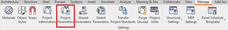
- Pressing the Project Parameters under the Manage button.
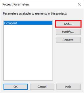
- Then pressing the Add… button.
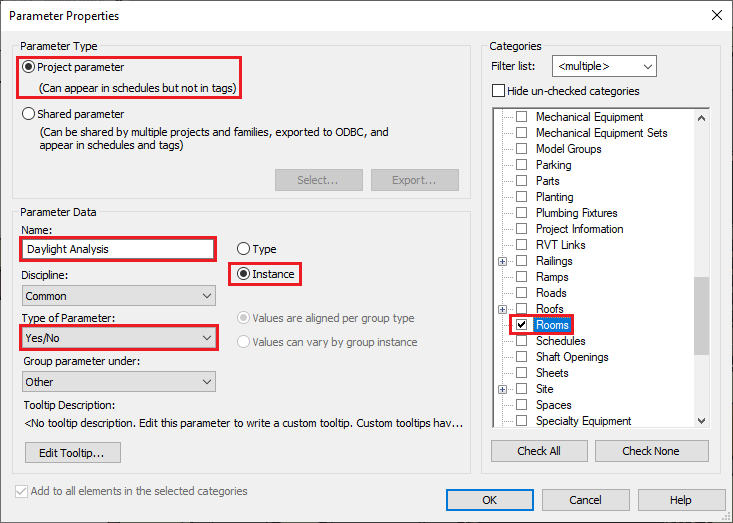
- Finally, under the Parameter Properties page, to create a proper Room Project Parameter that can be read by AftabRad, you should choose Yes/No Instance Project Parameter for the Rooms categories
in the model with one of these names:
“Daylight Analysis”, “daylight analysis”,
“Daylight_Analysis”, or “daylight_analysis”. (To know more, please check the
below image).
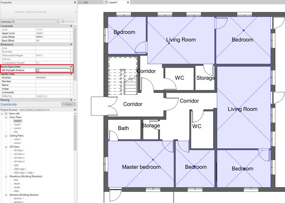
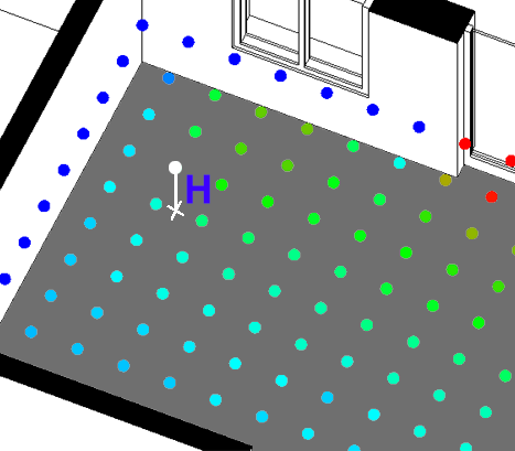
2- Then the first step is to select any rooms on which you want to do the daylight analysis in any Revit plan views.
The next step is to check
the “aft Daylight Analayis” or “Daylight Analysis” Room Project
Parameter that should be existed under the Room/Space Data inside Properties.
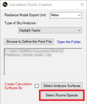
3- Now, press Select Rooms/Spaces button
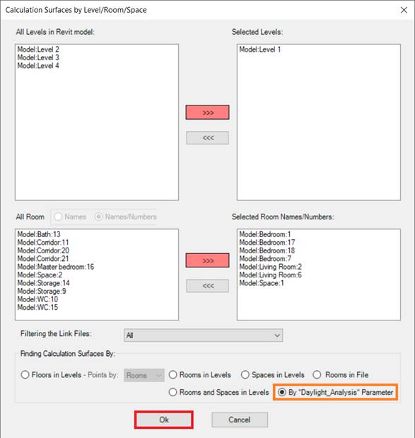
4- To create Calculation Points file based on project parameters, choose the “By Daylight_Analysis” Parameter radio button, and finally press the OK button.
5- To Define the Grid Point Interval Distances and Offset from the selected rooms floors and also Offset Distance from the select rooms surrounding walls, we should add the following inputs in the rtrace Settings page:
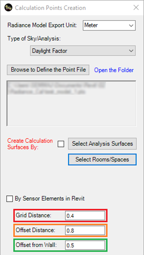
Grid Distance: Distance Between Grid Points: It is a spacing distance that the grid points distribution are made based on it.
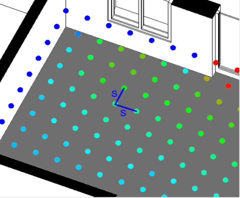
Offset Distance: Offset Distance from Surfaces (m): The offset distance (in meter) between the surface grids and the selected surfaces such as façades of the buildings or floors.
Offset
from Wall: Offset from Wall: Offset Distance: The distance from the walls of a
space in which the grid points are excluded when created.
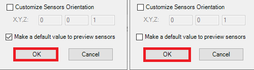
6- If you want to preview the selected grid points before doing the calculation, you should check the Make a default value to preview sensors checkbox.
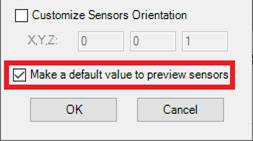
7- To finish and create a calculation Grid Point file, press the OK button.