AftabRad
Revit Add-in -> Revit2Radiace -> Rtrace Settings -> Select
Analysis Surfaces or Select Elements
To create the calculation points that are based on defining XYZ coordinate positions and directions, there are different methods that can be applied in this add-in.
However, this part of add-in provides two different ways that are explained in the below:
1. By selecting some surfaces in the model, it can create calculation points that are based on an offset distance from those surfaces.
2. By selecting some elements in the model, it can create calculation points that are based on an offset distance from some surfaces of those elements. Such surfaces are chosen by their orientation.
Therefore, to do the analysis we should do the following steps:
1- Press ExportToRadiance button in the AftabRad Add-in

2- To create Calculation Points file
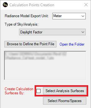
a. based on Selecting Analysis Surfaces, do the following steps:
i. Keep the checkbox next to the Calculation Surface by: unchecked. Then, press the Select Analysis Srf. Button.
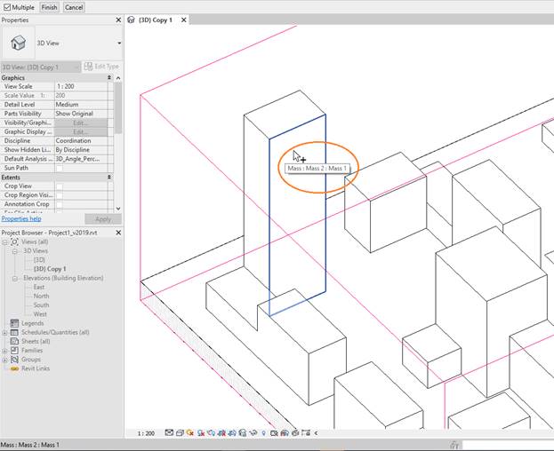
ii. Select those surfaces on which you want to make analysis
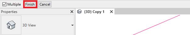
iii. Finally press the Finish button

b. based on Selecting Elements, do the following steps:
i. Checked the checkbox next to the Calculation Surface by:. Then, press the Select Elements Button.
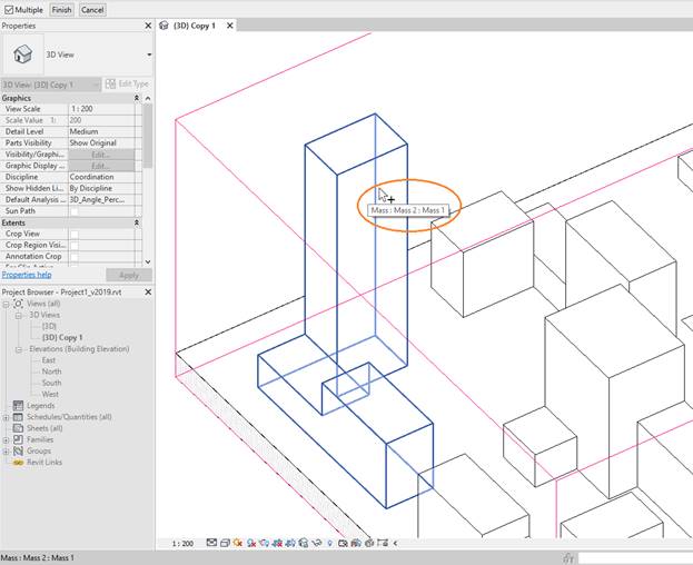
ii. Select those Elements on which you want to make analysis
iii. Finally press the Finish button
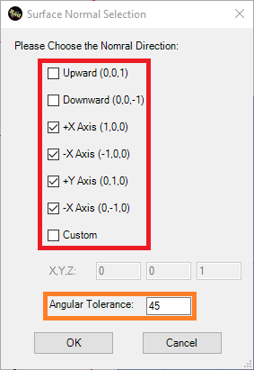
iv. Under the Surface Normal Selection, choose those surface normal orientations together with defining the angular tolerance for choosing the selected elements surfaces.
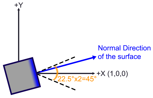
Regarding the Angular Tolerance, for example if we have a cubic model like the below image, and we choose +X Axis (1,0,0) and if we have 22.5° as Angular Tolerance, the below surface will be chosen.
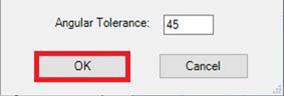
v. Finally press the OK button
3- To Define the Grid Point Interval Distances and Offset from the selected rooms floors, we should add the following inputs in the rtrace Settings page:
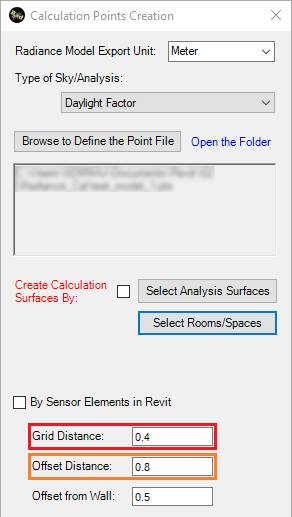
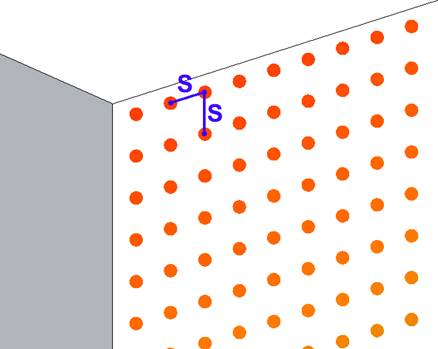
Grid Distance: Distance Between Grid Points: It is a spacing distance that the grid points distribution are made based on it.
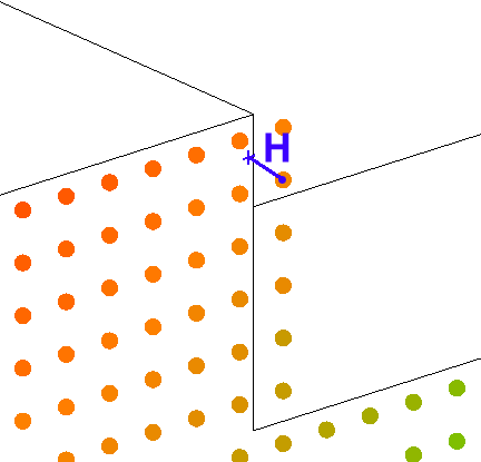
Offset Distance: Offset Distance from Surfaces (m): The offset distance (in meter) between the surface grids and the selected surfaces such as façades of the buildings or floors.
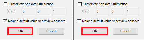
4- If you want to preview the selected grid points before doing the calculation, you should check the Make a default value to preview sensors checkbox.
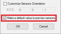
5- To finish and create a calculation Grid Point file, press the OK button.