AftabRad Revit Add-in -> Revit To
OpenFoam
Doing a CFD
analysis for interior or exterior is usually very expensive, time consuming and
more importantly needs at least some basic knowledge about CFD simulation
methods.
However, the
main goal of this part of add-in is to make this process easier for architects
and urban designers when working in early stages of the design process and only
dealing with the urban realms.
Therefore,
the main function of this command is to export the Mass, Generic model or
Topography elements into OpenFoam program that is is a free and open source Computational Fluid Dynamics (CFD)
Simulation Software and do some adjustment for the wind analysis
calculation. Moreover, in this RevitToOpenFoam command, its users can easily
find the dominant wind direction for the whole year, different seasons, or each
month separately by importing the relevant weather data file of the place. Â
Finally, the ultimate goal of this part of program is to do wind analyses for
outdoor spaces by defining the dominant wind direction and its average speed
together with some other parameters that are needed by OpenFoam.
Therefore, to do a CFD analysis for an outdoor space, we should do the following steps.
1- Press RevitToOpenFoam button in the AftabRad Add-in

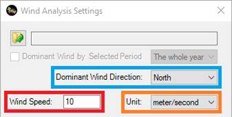
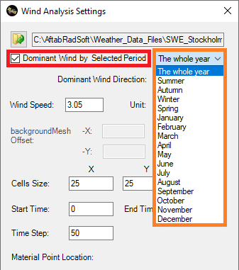
2- The second step in this
analysis is to define the wind direction and wind speed. There are two ways to
do that here.
-
The first method is to input both wind
direction, wind speed unit and wind speed manually.
-
The second method is to define the dominant
wind direction and wind speed with the help of using imported data from an EPW
weather data file of the place.
To do so, firstly we need to press the open EPW file button
and select an EPW file that is relevant to the place of the project.
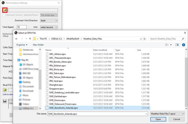
Then by checking the Dominant Wind by Selected Period checkbox,
and also defining one of the period options,
based on the input data from the selected EPW file, this adding
automatically finds the dominant wind direction and wind speed of the place.
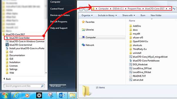
3- The third step to define
the openFoam/blueCFD-Core installation
folder. To do so, we should follow the below instruction.
-
Go to All Programs in Windows, then
find the Blue CFD-Core, and finally, by clicking on the Blue CFD-Core
Folder, the Blue CFD folder is opened.
-
Then, we should see the path that is needed
to be specified in the below text box. So, we need to copy that path into
clipboard.
-
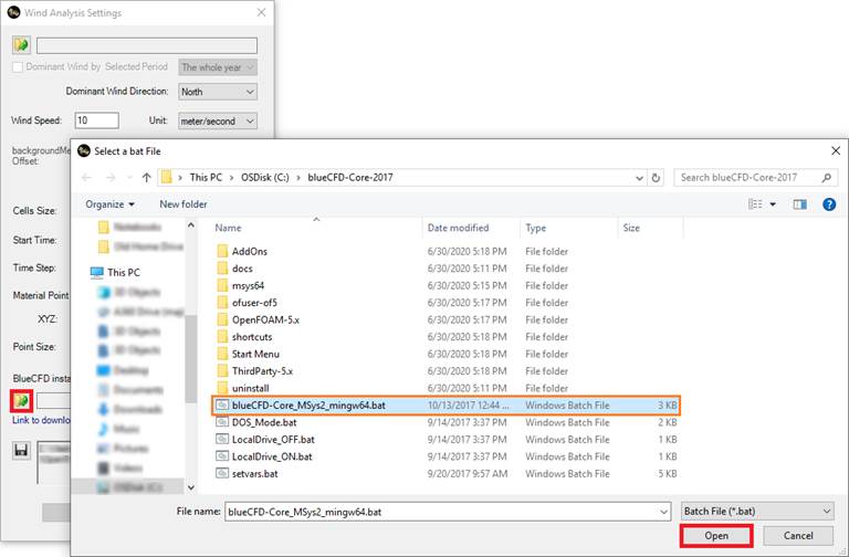
Now it is time to press the Open
button and select one of the batch files (for example choose blueCFD-Core_MSys2_mingw64.bat
file)
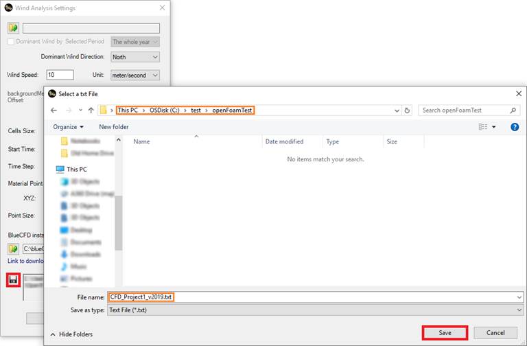
4- The fourth step to define
a folder where we want to save all the needed files there. So, press this Save
button and browse to define a folder to save.
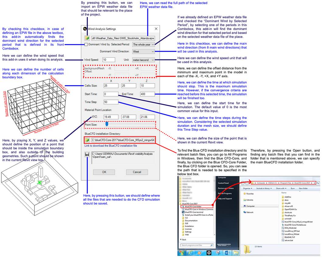
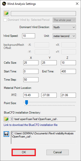
5- Now it is time to specify
the other parameters that exists and needed for this simulation. To know about
those parameters, please take a look at the below image.
6- The 6th step is to press
the OK button and export and save all needed files into where we already
specified.
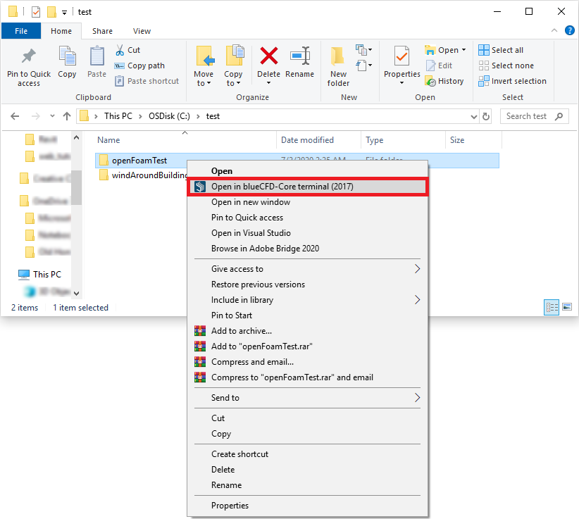
7- After finishing the export
process, the 7th step is to run the simulation. To do so, we should browse and
find the folder that included all the exported files for our CFD analysis.
After finding that folder, we
should use right click mouse on that folder and select Open in blueCFD-Core
terminal
 Â
Â
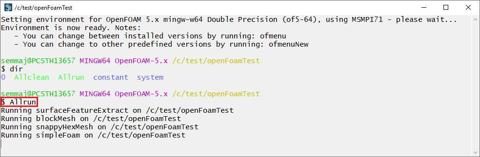
8- when the minGW x64
terminal is opened, by using dir, we can see all the files that are
exited in the folder.
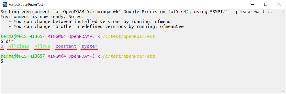
If
there are these files and directories (0, Allclean, Allrun, constant, system) in the folder, then the export should be successfully done.
9- to start the simulation,
we should write the Allrun and pressing Enter in the minGW x64
terminal.
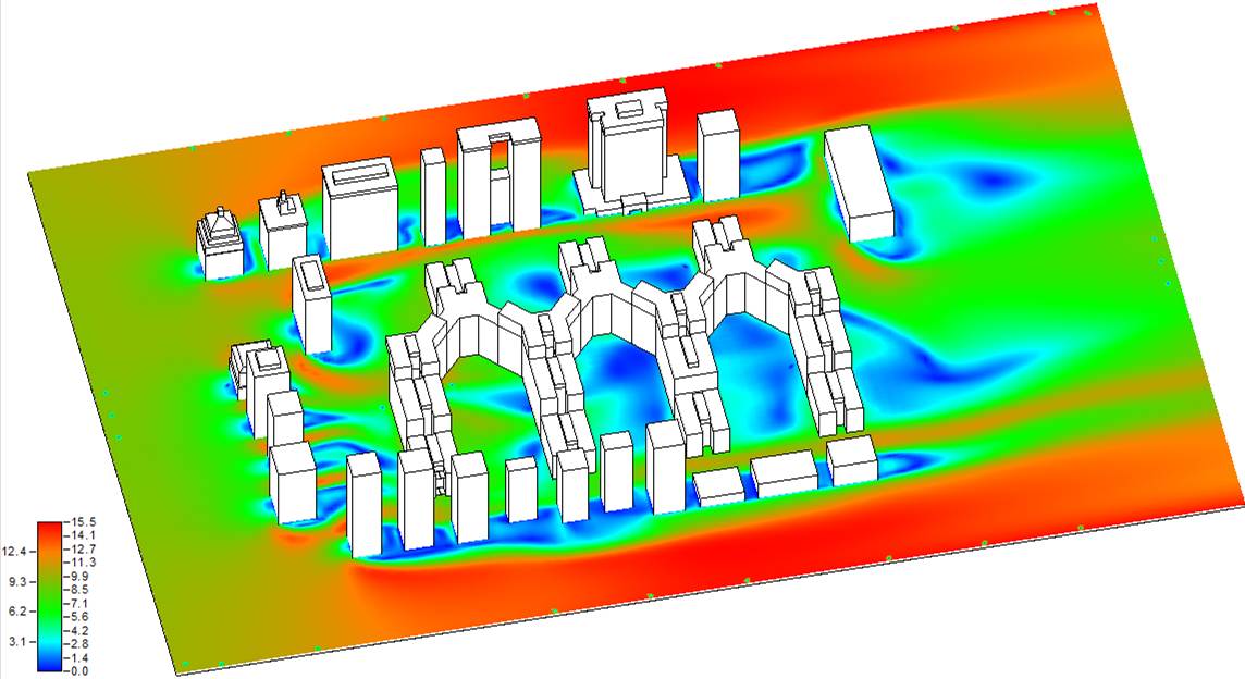
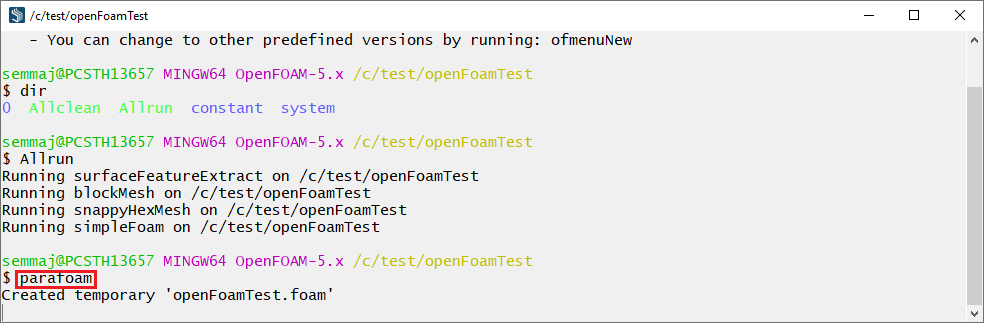
10- When the simulation is
finished, to visualize the calculation results inside Paraview program,
by writing the parafoam and pressing Enter in the minGW x64
terminal, the Paraview program will be opened.
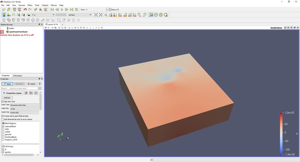
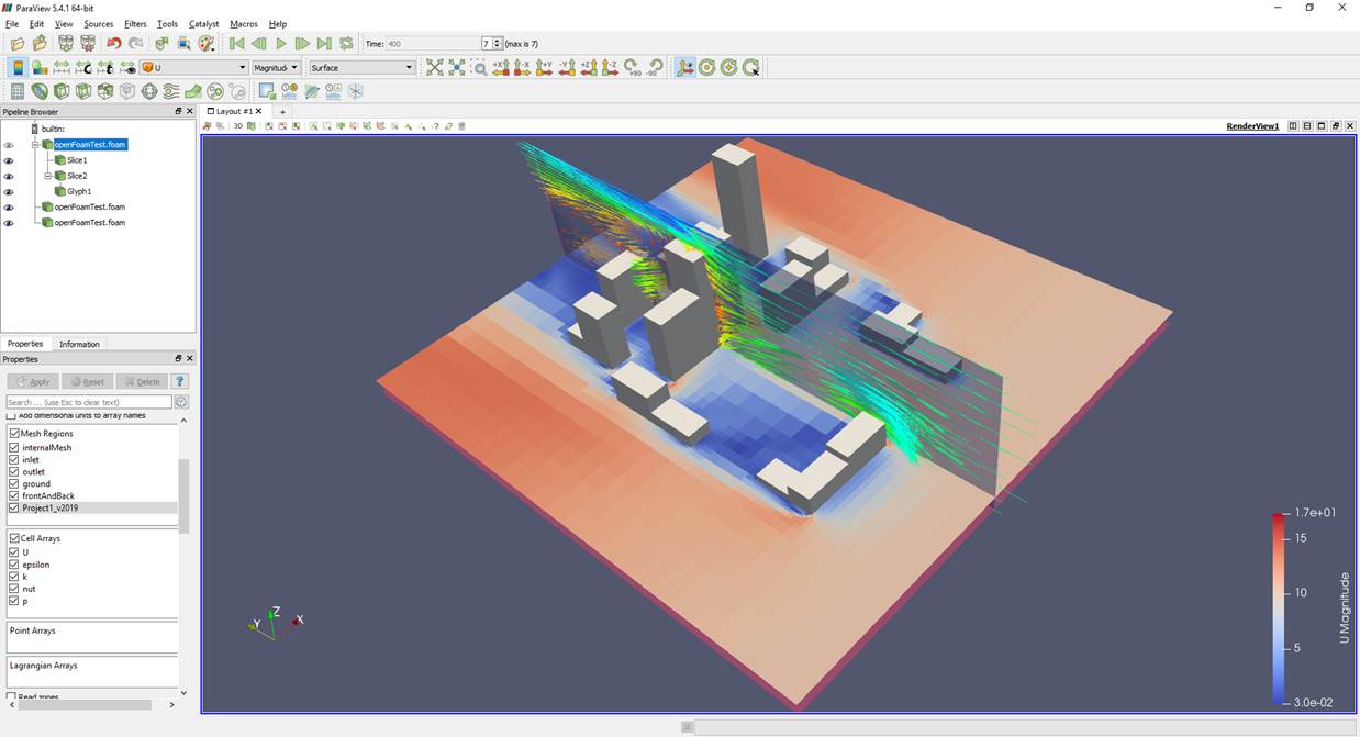
There are quite many tutorial
documents and videos for Paraview. One of the videos that can be useful
is from this link: https://youtu.be/LCjYMtcFB2k?t=352
11-
However, in order to present the results inside Revit, please follow the below
steps:
In order to create calculation points to measure wind speed, please
press the calculationPointsCreation button.

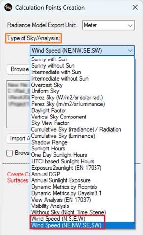
When the Calculation Points Creation page is opened, based
on the wind direction you already selected in step 2, please choose between Wind
Speed (N,S,E,W) and Wind Speed (NE,NW,SE,SW).
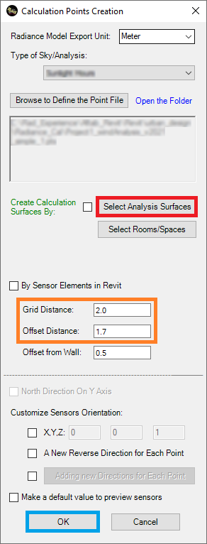
Then by pressing Select Analysis Surfaces and selecting the
above surfaces of such floors, we can create the calculation points to measure
wind speed.
-
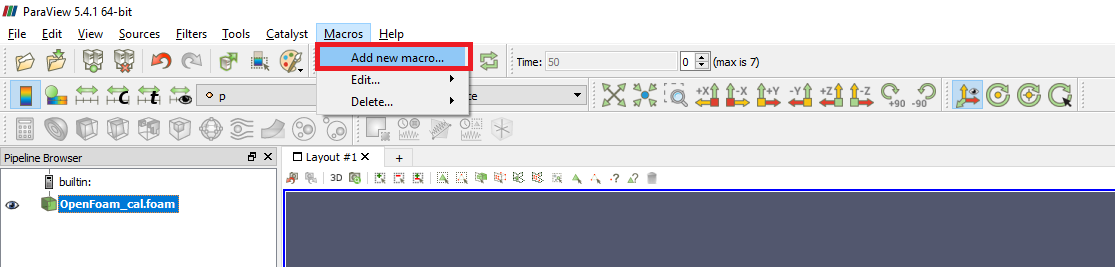
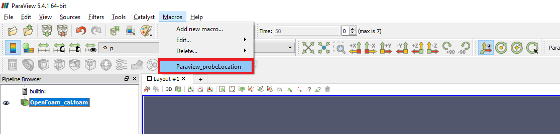
The next step
is pressing the Macros >> Add
new macro… inside Paraview
-
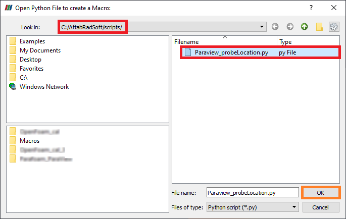
Then, please
go to C:\AftabRadSoft\scripts and select the Paraview_probeLocation.py
file
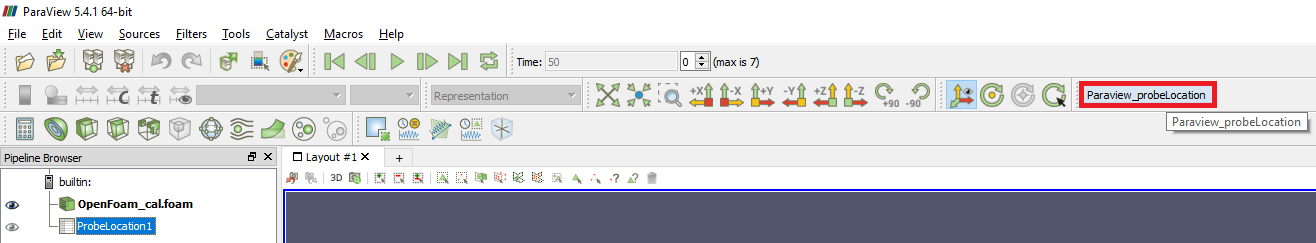
-
Next is to go
to Macros >> Add new macro…and click on Paraview_probeLocation
or press the Paraview_probeLocation in the menu
Or
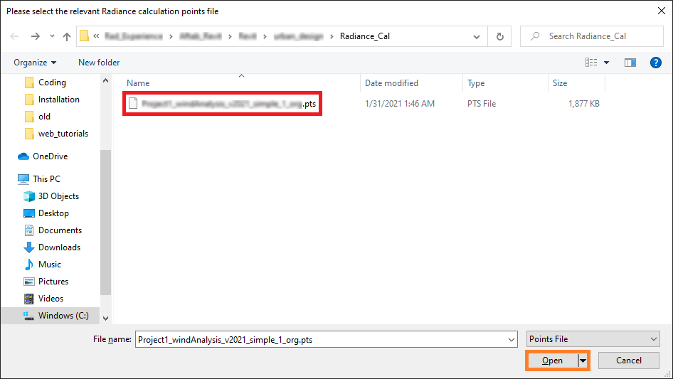
-
After
clicking on the Paraview_probeLocation, please select the relevant
Radiance calculation points file that is already created by calculationPointsCreation
in Aftab add-in.
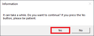
-
Now, if you
want to continue, you should press the Yes button. However, it can take
a while, so you should be patient.
-
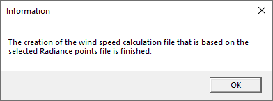
When a message like the one in the below pops up your screen, it means
that a new wind speed based data file is created.
12-
Now, it is time to import the wind speed based data into Revit.
Therefore, the next step is to press the importToRevit Button.

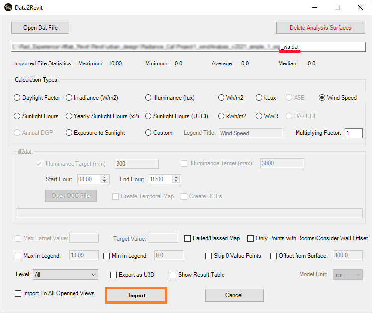
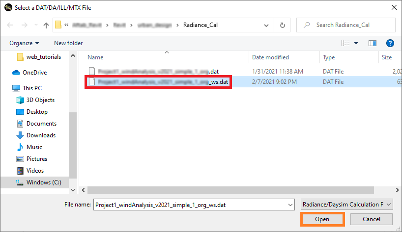
13-
In the Data2Revit page, please press the Open Dat File button, choose
the right dat file that is ended with _ws.dat.
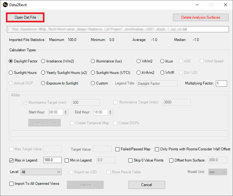
14-
Finally, press Import